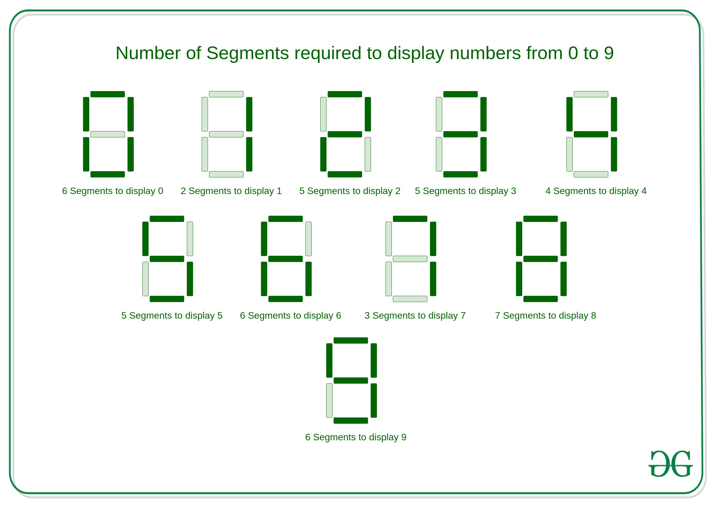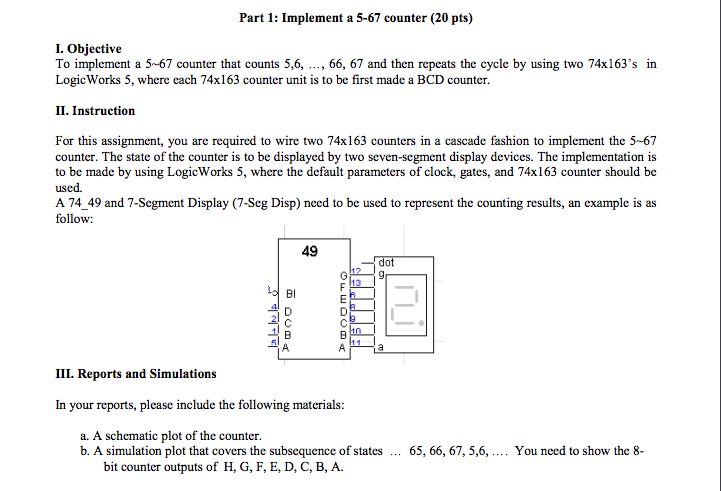

The 7-segment display for the tens digit must appear immediately to the left of that for the units digit, as shown below (some gap is necessary to allow for wiring). Figure 2 shows the correct segment assignment for each digit.

Note that there is some slight ambiguity in the correct segments to be displayed for each digit. This is not a trivial exercise and there will still be significant gates involved to exhibit this functionalityĥ. Marks will be deducted both for errors and for designs which use too many gates Label your signals as depicted in Figure 1, otherwise marks will be deducted.
#Logicworks 7 segment display software#
Your work must use Karnaugh Maps or appropriate software to make some attempt at minimizing the number of gates in the design. Marks will be deducted if a dot or greyed segment appears at any time.Ĥ. ? No dot or grey segment should ever be displayed. ? Two digits must be displayed for all inputs (blank is not equivalent to zero). Should be displayed when F is clicked on the hex display, then the tens digit 4 and units digit 1 should be displayed. For example, when the user clicks on the hex display, eg 4, then the tens digit 2 and units digit 1 Each display will show one decimal digit. The input will be from a hex keypad and the output shown on two 7-segment displays. Your design should be implemented in Logic Works for Windows.ģ. Here, t is a 4-bit cardinal, i.e., 0 t 15. For this assignment you are to design and construct a combinatorial circuit to implement and display the function ) ) in decimal.Ģ. If fewer than two are in the on position, the system is disabled.” Use binary switches and probes as inputs and outputs respectively in Logic Works.ġ. To enable the system, switches in at least two of the panel must be in the ON position. Design a combinatorial circuit that meets these requirements: “An alarm system has three different control panels in three different locations. Create a circuit in Logic Works using at most three gates that is equivalent to this expression.Ĥ.

Create the Truth Table for the following Boolean expression. Create the Truth Table to identify the outputs for ).ģ. Use binary switches and probes as inputs and outputs respectively in Logic Works.Ģ. Create a combinatorial circuit that implements the binary functionĭo not simplify the binary expression. TASK SET 2: COMBINATORIAL CIRCUITS (25 MARKS)ġ. Then rewrite this statement with only and. Use logical equivalences of p q and p q to rewrite the statement: Simplify the following binary expression. TASK SET 1: BOOLEAN ALGEBRA AND SET THEORY (15 MARKS)ġ. The circuits required in Task Sets 2 and 3 are to be implemented using the Logic Works 4.0 application available on the Laboratory machines. There are three sets of tasks you must complete based on the work up to end of Week 5.


 0 kommentar(er)
